
4-Piece Content Strategy for CoolingTec
Website Blog | LinkedIn Long-form | LinkedIn Short Posts x2
Source: Original article on thick-core plate-fin heat exchanger vacuum brazing
Wuxi BAP Cooling Tech Co., Ltd | July 2026
Photo: Industrial cooling system infrastructure
Content Overview
| # | Type | Title | Word count |
| 1 | Website Blog | How to Improve Vacuum Brazing Yield for Thick-Core Plate-Fin Heat Exchangers | ~1600 words |
| 2 | LinkedIn Long-form | From 78% to 96%: Solving a Vacuum Brazing Yield Problem | ~1300 chars |
| 3 | LinkedIn Short Post A | The “Thick-Thin-Thick” Trap | ~500 chars |
| 4 | LinkedIn Short Post B | 6 Fixes for Vacuum Brazing Defects | ~600 chars |
All images in this document are either generated charts (copyright-free) or stock photos from Pexels (free license, no attribution required).
Piece 1: Website Blog (SEO)
Primary keyword: vacuum brazing thick-core plate-fin heat exchanger
Secondary keywords: aluminum vacuum brazing, plate-fin brazing defects, heat exchanger manufacturing quality
Meta description: A systematic guide to improving vacuum brazing yield for thick-core aluminum plate-fin heat exchangers — from defect analysis to process optimization, with a real case study showing 78% to 96% improvement.
How to Improve Vacuum Brazing Yield for Thick-Core Plate-Fin Heat Exchangers
When your plate-fin heat exchanger core uses thick partition plates (>=1mm) with ultra-thin internal fins (0.2-0.3mm), vacuum brazing stops being routine. It becomes a thermal balancing act.
At Wuxi BAP Cooling Tech, we learned this the hard way with a 1.5mm-plate oil cooler that shipped at just 78% first-pass yield. Six months of process optimization later, we hit 96%. Here is exactly how — and the principles that apply to any heavy-core aluminum brazing job.
Photo: Metal welding process in workshop
1. The Root Problem: “Thick-Thin-Thick” Thermal Lag
In a large-core plate-fin heat exchanger, the core is an alternating stack:
- Thick partition plates: thick partition plates (>=1mm) — high thermal mass, slow to heat
- Thin fins: ultra-thin fins (0.2-0.3mm) — low thermal mass, heat up fast
- Side bars: side bars / headers — another heat sink
This creates a temperature gap during ramp-up. By the time the thin fins reach brazing temperature (577-590C for Al-Si filler), the thick plates may still be 25-35C behind. Result:
- filler metal melts on the fin side but has not wetted the plate surface → incomplete brazing (cold joint)
- operator extends soak time to compensate → fin erosion or melting
- uneven cooling → core distortion, warping
| This is not a material problem. It is a heat transfer problem. |
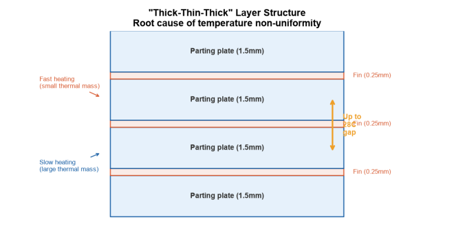
Figure 1: “Thick-thin-thick” alternating layer structure creates uneven heating during vacuum brazing.
2. Five Defects You Will See at Low Yield
| Defect | Root cause | Consequence |
| Incomplete brazing | Plate temperature too low at filler melting window | Leak under pressure test |
| Fillet erosion | Fin overheating; liquid filler dissolves fin material | Weakened or collapsed fins |
| Fin buckling / collapse | High-temperature strength loss + excessive clamping pressure | Flow blockage and thermal performance drop |
| Core distortion | Thermal stress + improper fixture | Dimensional out-of-spec, fit-up failure |
| Surface oxidation | Vacuum leak or insufficient vacuum level | Poor appearance, compromised sealDefect Root cause Consequence Incomplete brazing Plate temperature too low at filler melting window Leak under pressure test Fillet erosion Fin overheating; liquid filler dissolves fin material Weakened or collapsed fins Fin buckling / collapse High-temperature strength loss + excessive clamping pressure Flow blockage and thermal performance drop Core distortion Thermal stress + improper fixture Dimensional out-of-spec, fit-up failure Surface oxidation Vacuum leak or insufficient vacuum level Poor appearance, compromised seal |
Figure 2: Relative frequency of common defects in thick-core vacuum brazing.
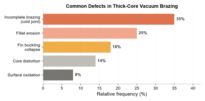
Photo: Close-up of aluminum bars (Pexels – free license)
3. Six Process Fixes That Moved Us from 78% to 96%
Figure 3: The 6-step process improvement framework applied to thick-core brazing.
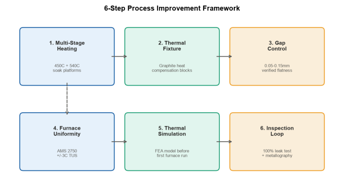
3.1 Multi-Stage Heating — Not One Ramp to Target
Single-ramp heating is the most common mistake. The fix: step-and-hold thermal equalization.
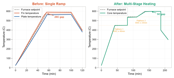
| Before (low yield): Room temp → fast ramp → 590C soak → cool Result: 28C plate-to-fin temperature gap After (high yield): Room temp → 10C/min → HOLD 450C x 40min → 3-5C/min → HOLD 540C x 25min → 3C/min → 598C soak x 30min → controlled cool Result: 5C gap across the core |
Rule of thumb: Set 1-2 soak platforms below solidus (for 3003/6061 with Al-Si filler: ~450C and ~540C). Soak time scales with core thickness — 30-90 minutes for the first platform.
Cool-down matters too. After brazing, purge with high-purity N2 or Ar. Keep cooling rate below 10C/min through 450C to avoid thermal stress cracking in thick sections.
Figure 4: Temperature profile comparison — single ramp (left) vs. multi-stage heating (right).
3.2 Fixture as a Thermal Tool — Not Just a Clamp
A brazing fixture does two jobs: mechanical constraint AND thermal redistribution.
| Fixture strategy | How it helps |
| Graphite plates | Match CTE with aluminum; act as heat spreaders |
| Heat-sink blocks on thick areas | Slow down fast-heating fin zones, redirect heat to plates |
| Elastic clamping (0.05-0.2 MPa) | Maintain contact without crushing softened fins |
| Support cradle for vertical loading | Prevent creep sagging in tall cores |
Key insight: too much clamping pressure blocks capillary flow of filler metal. Use spring-loaded or graphite-weighted systems that maintain light, even pressure as the stack expands.
3.3 Brazing Material and Gap Control
- Prefer: double-clad sheet (e.g., 4004/3003/4004) with 8-15% clad ratio. For thick plates, go to the upper end.
- Supplement with: foil (0.1-0.2mm) at large-gap joints (plate-to-header, thick side bars). Pre-cut strips — keep them away from fin channels.
- Assembly gap: 0.05-0.15mm. This is the capillary sweet spot. Check plate flatness before stacking (<=0.03mm / 100mm). Anything worse → flatten or match-grind.
3.4 Furnace Temperature Uniformity
Standard AMS 2750 furnace survey (TUS): effective heating zone must hold +/-3C.
Load thermocouples directly on the workpiece — minimum 3-5 per load, placed at: thick plate center, thin fin zone, top and bottom faces. Use the coldest reading to determine when soak time starts.
3.5 Thermal Simulation Before You Light the Furnace
For new large-core designs, run a transient FEA thermal model first. It will show you:
- maximum temperature lag between plate and fin
- optimal platform temperatures and durations
- hot/cold spots in the load
In our case, simulation predicted a 35C lag at 450C without a soak platform. Extending the 450C hold to 60 minutes closed the gap to 15C. That one change saved 3 furnace trials.
Photo: Engine block in workshop setting (Pexels – free license)
3.6 Inspection That Drives the Feedback Loop
| Method | What it catches | Frequency |
| 100% pressure / leak test | Brazing voids → leak locations | Every unit |
| Cross-section metallography | Braze ratio (target >=95%), erosion depth (<=25% of fin thickness) | First article + periodic |
| Industrial CT | Internal bond quality, fin deformation — non-destructive | High-value or prototype units |
Map leak locations to core position. If leaks cluster at edges or center, your fixture or thermal profile has a pattern — fix it at the source.
4. The Numbers: Before vs. After
| Metric | Baseline | After optimization |
| Qualification rate | 78% | 96% |
| Core temperature spread | +/- 28C | +/- 5C |
| Braze ratio (metallography) | ~85% | 97% |
| Brazing temperature | 590C | 598C |
| Total cycle time | Shorter (unpredictable) | Longer but repeatable |
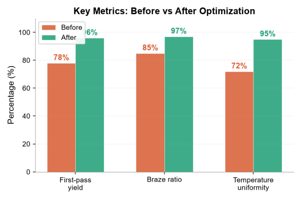
Figure 5: Key metrics comparison — before vs. after process optimization.
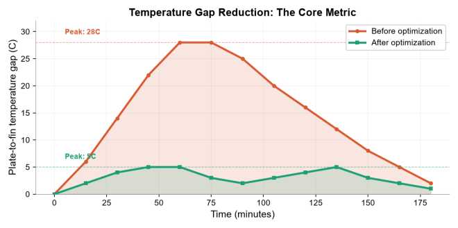
Figure 6: Temperature gap (delta-T) between thick plates and thin fins, before and after optimization.
| The counterintuitive part: lower peak temperature + shorter soak + controlled ramp = higher yield. At 590C with a 28C spread, fins were overheating while plates were still cold. Dropping to 598C with equalized temperatures meant the entire joint hit the brazing window simultaneously. |
5. Sustaining High Yield
- Lock the optimized profile into standard process cards per product family
- Monitor load thermocouple data with SPC control charts (braze ratio, leak rate, key soak temperatures)
- Re-survey furnace uniformity every 6 months or after any maintenance
- For every new thick-core product, run simulation first, confirm with first-article metallography
Conclusion
Thick-core plate-fin brazing yield is not a mystery — it is a system with measurable inputs. Control the temperature gap, control the fixture, control the gap, and inspect what you control. The result is 96%+ repeatable yield, even on 2-meter class cores.
| Need a reliable plate-fin heat exchanger for your system? We manufacture these in-house — from core design through vacuum brazing to final pressure test. Contact us for specifications and pricing → coolingtec.com.cn/contact |
Piece 2: LinkedIn Long-form Article
Publishing: Friday, 8:30 AM EST | Image: Temperature gap chart
From 78% to 96%: Fixing a Vacuum Brazing Yield Problem on a Thick-Core Oil Cooler
We were losing 22% of every batch. Same furnace. Same alloy. Same operator. The problem was invisible.
Our oil cooler used 1.5mm partition plates with 0.25mm internal fins. In vacuum brazing, that creates a heat transfer mismatch: the thin fins hit 590C long before the thick plates catch up. Result: filler melts where you do not want it, and will not flow where you need it.
What we tried first (and got wrong):
- Crank up the temperature to “make sure everything melts” → This just eroded the fins faster
What actually worked:
A 6-point process overhaul:
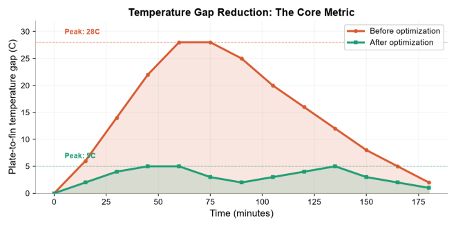
Temperature gap reduction: the core metric that drove yield improvement.
The result:
- Core temperature spread: +/- 28C → +/- 5C
- Braze ratio: 85% → 97%
- First-pass yield: 78% → 96%
The biggest lesson: for thick-core heat exchangers, the furnace setpoint does not matter nearly as much as what the core itself is actually seeing. That is what load thermocouples tell you.
We now run this protocol on all large-core jobs. Consistent results. Repeatable quality.
What is the most counterintuitive thing you have learned about a manufacturing process? I would like to hear from other engineers.
#HeatExchanger #VacuumBrazing #PlateFinHeatExchanger #ManufacturingEngineering #ThermalManagement #OilCooler #HydraulicSystems #AluminumBrazing #QualityControl #ProcessImprovement #IndustrialManufacturing #B2B
Piece 3: LinkedIn Short Post A (Pain Point)
Publishing: Wednesday, 10:00 AM IST | Image: Structure diagram
The “Thick-Thin-Thick” Trap
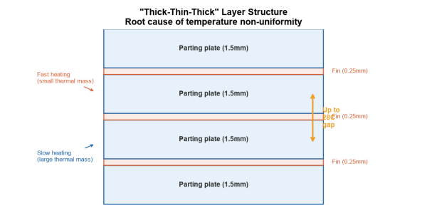
Cross-section: alternating thick plates and thin fins create uneven heating.
In a plate-fin heat exchanger core, you are stacking 1.5mm aluminum partition plates against 0.25mm internal fins. In the vacuum furnace, they do not heat up together.
The fins reach brazing temperature 25-35C ahead of the plates. Your filler metal melts on one side before the other surface is ready to wet.
That is how you get:
- Braze ratio below 85%
- Leak test failures at the corners
- Fins that look “eaten” under a microscope
We fixed this with one change: stop single-ramp heating. Insert a 450C soak platform. Let the thick plates catch up.
| Temperature spread went from +/- 28C to +/- 5C. Yield went from 78% to 96%. Same furnace. Same alloy. Different thermal strategy. |
Been through a similar process fix? What worked for you?
#HeatExchanger #VacuumBrazing #PlateFin #Manufacturing #ThermalManagement #ProcessEngineering #HydraulicSystems #AluminumBrazing
Piece 4: LinkedIn Short Post B (Checklist)
Publishing: Thursday, 8:30 AM EST | Image: 6-fix infographic
6 Fixes for Vacuum Brazing Defects in Heavy-Core Heat Exchangers
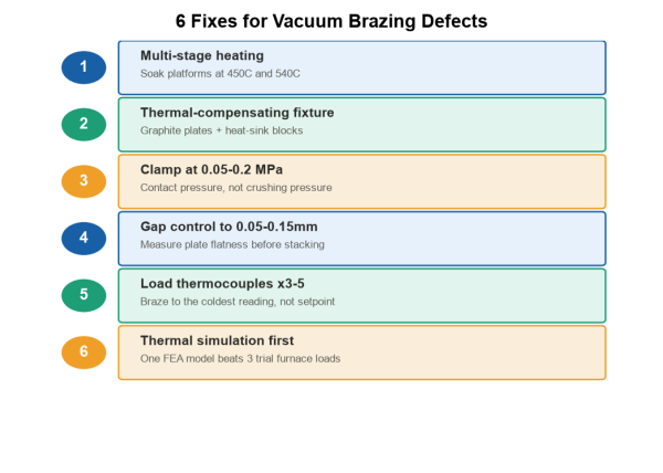
Infographic: 6 process fixes for vacuum brazing defects.
If your brazing yield on thick-plate cores is stuck below 85%, here is the checklist. Pick the one you are not doing yet:
- Multi-stage heating — 1-2 soak platforms below solidus to equalize core temperature
- Thermal-compensating fixture — graphite plates + heat-sink blocks redirect heat to cold zones
- Clamp at 0.05-0.2 MPa — contact pressure, not crushing pressure. Filler needs capillary space.
- Gap control to 0.05-0.15mm — measure plate flatness before stacking
- Load thermocouples at 3-5 points per core — braze to the coldest thermocouple, not the furnace setpoint
- Thermal simulation before first run — one FEA model beats three trial-and-error furnace loads
These six steps took us from 78% to 96% first-pass yield on a 1.5mm-plate oil cooler. The principles scale to any large-core aluminum brazing job.
| Save this for your next thick-core run. |
#HeatExchanger #VacuumBrazing #ManufacturingChecklist #PlateFinHeatExchanger #ProcessOptimization #Engineering #QualityControl #AluminumBrazing #IndustrialCooling #B2B
Appendix: Publishing Schedule
| Week | Wed | Thu | Fri | Notes |
| Week 1 | Short Post A (pain point) | — | — | Test topic engagement |
| Week 2 | — | Short Post B (checklist) | — | High save rate expected |
| Week 3 | — | — | Long-form article | Full case study |
| Week 4 | Blog goes live | — | — | SEO long-tail content |
Hashtag Strategy
| Layer | Purpose | Examples |
| Industry (3-4) | Reach target industry buyers | #HydraulicSystems #WindPower #ConstructionMachinery #CompressedAir |
| Product (3-4) | Match search intent | #HeatExchanger #PlateFinHeatExchanger #OilCooler #AluminumRadiator |
| Technical (2-3) | Scene-specific reach | #VacuumBrazing #AluminumBrazing #ThermalManagement |
| Broad (1-2) | Expand reach | #Manufacturing #Engineering #B2B #IndustrialCooling |
Image Credits
All charts and diagrams: Generated by CoolingTec (copyright-free)
Stock photos: Pexels.com (free license, no attribution required)
– Industrial cooling system: Photo 37913513
– Metal welding process: Photo 36522037
– Aluminum bars: Photo 25285744
– Engine block: Photo 36598766
– Metal pipes/tubing: Photo 19825178