
Every brazing reject costs more than the part. You have already paid for the material, the cleaning, the stacking, the furnace hours and the inspection. A leak at helium test sends the core back to the start of that list.
The good news: brazing defects are not random. Across our own production we catalogued 14 failure modes, and once you sort them by mechanism most collapse into a short list of root causes. This guide lists all 14 — what they look like, why they happen, and the first fix worth trying.
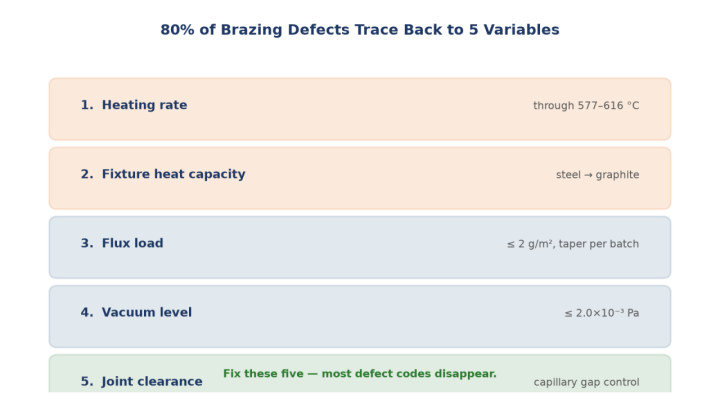
The Five Variables Behind Most Defects
Before the list, the pattern. Five process variables account for the large majority of defect codes:
- Heating rate through the solidus–liquidus band (577–616 °C for standard Al-Si filler)
- Fixture heat capacity — heavy steel fixtures slow the ramp and extend the danger zone
- Flux load — aluminium vacuum brazing Mg flux is typically ≤ 2 g/m²
- Vacuum level — target ≤ 2.0×10⁻³ Pa; anything worse leaves oxide behind
- Joint clearance — capillary action only works in a narrow gap window
Defects that look completely different on the shop floor often share one of these five. That is why a defect-name approach to troubleshooting is slower than a variable approach.
The Danger Zone: Why Ramp Rate Comes First
Between solidus and liquidus the filler metal is partly molten. Hold the assembly there too long and three things go wrong at once: low-melting elements vaporise out of the filler, the remaining filler composition shifts, and surface tension drops so the liquid spreads where it should not.
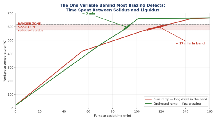
The fix is counter-intuitive if you were taught to heat gently: ramp slowly to ~500 °C to equalise, then cross 577–616 °C as fast as the furnace allows, and do your soaking above liquidus. Most spreading, erosion and incomplete-melt rejects disappear with that change alone.
Group A — Filler Flow Defects
1. Excessive filler spreading
A thin film of filler covers the base metal away from the joint. Cause: clamping too loose so the gap opens, fixture stiffness too low so heat and gravity widen the gap, or excess flux improving wetting beyond control. Large batch loads and slow ramps make it worse by extending liquid dwell.
Fix: increase clamping force, stiffen the fixture, lighten it (hollow it out, substitute graphite for steel), cut flux load and taper it down batch over batch, and shorten the hold.
2. Base metal erosion
The molten filler dissolves the parent metal and leaves a depression. Cause: filler and base metal forming a low-melting eutectic, or a long dwell in the danger zone that lets that reaction run.
Fix: change filler grade, ramp fast near the melting point, reduce batch load and fixture mass, lower peak temperature, shorten the hold.
3. Incomplete filler melting
The surface of the filler melts, the core does not. Cause: slow ramp through the danger zone vaporises the low-melting fraction, the remainder’s melting point rises above the peak temperature.
Fix: staged ramp with a fast final stage, isothermal hold at ~500 °C to remove thermal lag, lighter fixtures, smaller batch load.
4. Filler loss
Filler runs out of the joint instead of staying in it. Cause: excessive temperature or hold time, filler placed where it cannot develop capillary action, or a locally oversized gap.
Fix: reposition the filler, control local clearance, reduce peak temperature and hold time.
Group B — Joint Filling Defects
5. Missing braze / skip
No filler in the seam, or filler that melted and drained away. Cause: insufficient filler volume, gap opened by a ramp so fast the part distorted, flux overdose making the filler too fluid, or slow ramp through the danger zone shifting filler composition.
Fix: add filler, increase clamping force, add a stress-relief anneal before brazing or stage the ramp with a fast section above 500 °C, reduce flux, lighten the fixture.
6. Poor gap filling
Part of the joint is unfilled. Causes span joint design, part cleanliness, flux activity, filler wetting, filler placement, and uneven or too-low temperature. When this shows up, check joint design and cleaning first — they are the cheapest to correct.
7. Flux inclusion in the seam (钎缝夹渣)
Flux trapped inside the solidified seam. Cause: too much or too little flux, wrong clearance, filler fed from both sides of the joint, mismatch between flux and filler melting ranges, flux density too high, or uneven heating.
Group C — Porosity
8. Pinholes and blowholes
Gas bubbles trapped as the filler solidifies. Cause: vacuum worse than the 2.0×10⁻³ Pa target, high furnace pressure resisting bubble escape, or filler with too high a content of high-vapour-pressure elements.
Fix: set a hold plateau just below the filler melting point to let furnace pressure settle, and specify filler with lower high-vapour-pressure content.
9. Gas porosity in the seam
Same family as above but driven by preparation: wrong joint clearance, parts not clean before brazing, weak flux or shield-gas de-oxidation, or filler outgassing / overheating.
Group D — Strength and Cracking
10. Low braze strength
The seam holds but pulls apart below specification. Causes: hold too short for diffusion, slow ramp through the danger zone volatilising alloying elements, vacuum too poor or leak rate too high so oxide re-forms, oxide not fully removed, over-etching in alkaline cleaning altering filler composition, or too little flux.
Fix: extend the hold, stage the ramp, lower vacuum pressure and check equipment leak rate, verify cleaning strength (keep alkaline etch near 60 °C and separate filler from base metal if composition drift is suspected), increase flux.
11. Seam cracking
Cracks in the braze seam itself. Cause: dissimilar base metals with mismatched thermal expansion, uneven heating causing uneven contraction, part movement while the filler solidifies, wide solidification range, or a brittle seam.
12. Base metal cracking
Cracks in the parent material. Cause: overheating or burning, filler penetrating grain boundaries and forming brittle phases, uneven heating or over-rigid clamping, pre-existing internal stress, or a material pair with a large expansion mismatch and low ductility.
13. Severe base metal attack
An advanced form of defect 2 — the same mechanism taken further by excessive temperature, excessive hold time, violent filler/base interaction, or too much filler metal. Treat it as erosion with all three aggravating factors to reduce at once.
Group E — Distortion
14. Distortion of the brazed assembly
Warping from fast heating releasing stress unevenly, thermal stress, fast cooling, or insufficient fixture stiffness and clamping. Fix: stress-relief anneal before brazing, staged ramp with an isothermal plateau and fast final approach, controlled cooling (slow below solidus), and a stiffer, more accurate fixture.
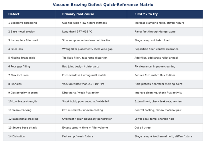
Quick-Reference Matrix
When a reject lands on the bench, work down this table — first fix to try, cheapest first.
How We Keep Defect Rates Down
A defect list is only useful if it feeds back into process control. Our brazing quality system runs on five closed-loop controls — material and cladding verification, cleaning, assembly and joint clearance, vacuum and thermal profile, and post-braze inspection. Each defect code maps to a control point, and every control point has an owner and a record.
If you are sourcing aluminum plate-fin cores — oil coolers, charge air coolers, radiators — and want to know how a specific defect risk is controlled on your part, send us the drawing and the operating conditions. We will tell you where the risk is before you place the order.
────────────────────────────────────────────────────────────